CAD to Unreal Engine 5
Introduction
A comprehensive guide on converting CAD files into Unreal Engine 5 (UE5) compatible formats, specifically focusing on the fischertechnik factory model. This guide covers the entire process from exporting the CAD model to importing it into UE5, including necessary adjustments and optimizations for a seamless workflow.
Example Use Case
The example used in this guide is the fischertechnik factory model, which is a complex assembly of various components. The goal is to export this model from Fusion 360, optimize it in Blender, and import it into Unreal Engine 5 where the digital twin of the factory can be visualized and interacted with. The process will demonstrate how to handle common issues encountered during the export and import process, ensuring a smooth transition from CAD to a game engine environment.
Glossary
| Term | Definition |
|---|---|
| CAD | Computer-Aided Design, a software used for creating precise drawings and technical illustrations. |
| STEP | A file format used for 3D CAD data exchange, allowing different CAD software to share models. |
| FBX | A file format used for 3D models, animations, and textures, commonly used in game engines like Unreal Engine. |
| GLB | A binary version of the GLTF (GL Transmission Format) file format, used for 3D models and scenes. |
| OBJ | A file format used for 3D models, commonly used in various 3D software and game engines. |
| Blender | A free and open-source 3D modeling software used for creating and editing 3D models, animations, and visual effects. |
| Unreal Engine 5 | A powerful game engine developed by Epic Games, used for creating high-quality games and interactive experiences. |
| UV Mapping | The process of projecting a 2D image texture onto a 3D model's surface, allowing for detailed textures and materials. |
| Vertices | Points in 3D space that define the corners of a polygon or mesh. They are used to create the shape of a 3D model. |
| Edges | Lines connecting two vertices, forming the outline of a polygon or mesh. |
| Mesh | A collection of vertices, edges, and faces that defines the shape of a 3D object in space. |
| Material | A set of properties that define how a 3D model interacts with light, including color, texture, and reflectivity. |
| Texture | A 2D image applied to a 3D model's surface to give it color and detail. |
| LOD | Level of Detail, a technique used in 3D graphics to reduce the complexity of a model based on its distance from the camera, improving performance without sacrificing visual quality. |
| UV Unwrapping | The process of mapping a 3D model's surface to a 2D plane for texture application, allowing for precise control over how textures are applied to the model. |
| TXT controller | A fischertechnik controller used for controlling and monitoring the factory model, providing connectivity to the fischertechnik cloud and other components. |
Requirements
Software
| Software | Description |
|---|---|
| CAD Software (Fusion 360) | Recommended for importing .STEP files and exporting to .FBX, .GLB, or .OBJ formats. Other CAD software can be used if they support these formats. |
| Unreal Engine 5 | Latest version required for the import process. Ensure you have the latest version installed on your system. |
| Blender | Required for all adjustments and optimizations. Install the latest version for best compatibility. |
Note
Although the guide focuses on Fusion 360 and Blender, the process can be adapted to other CAD software and 3D modeling tools. The key is to ensure that the software used can handle the required file formats and provide the necessary features for optimization.
Recommended Hardware
| Component | Requirement |
|---|---|
| Operating System | Windows 10 64-bit version 1909 revision .1350 or higher, or versions 2004 and 20H2 revision .789 or higher |
| Processor | Quad-core Intel or AMD, 2.5 GHz or faster |
| Memory | 32 GB RAM |
| Graphics RAM | 8 GB VRAM |
| Graphics Card | DirectX 11 or 12 compatible graphics card with the latest drivers |
Recommended Knowledge
The tasks we are about to perform are not very complex, but some knowledge of CAD software and 3D modeling is recommended. However, to fully understand the process, it is recommended to have some knowledge of the following topics:
- CAD Software: Familiarity with the CAD software used for exporting the model is essential. Understanding how to navigate the software, manipulate objects, and export files is crucial for a smooth workflow.
- 3D Modeling: Basic knowledge of 3D modeling concepts, such as meshes, UV mapping, and materials, will help in understanding the optimization process in Blender.
- Unreal Engine 5: Familiarity with Unreal Engine 5, including its interface, importing assets, and basic project setup, will be beneficial for a smooth transition from Blender to UE5.
Resources
- Unreal Engine 5 System Requirements
- Unreal Engine 5 Download
- Blender System Requirements
- Blender Download
- Fusion 360 System Requirements
- Fusion 360 Download
Exporting the CAD Model
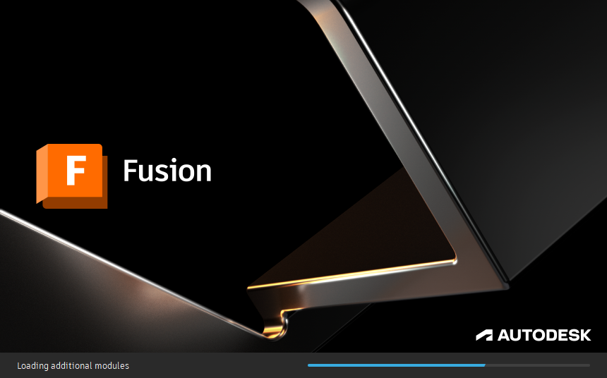
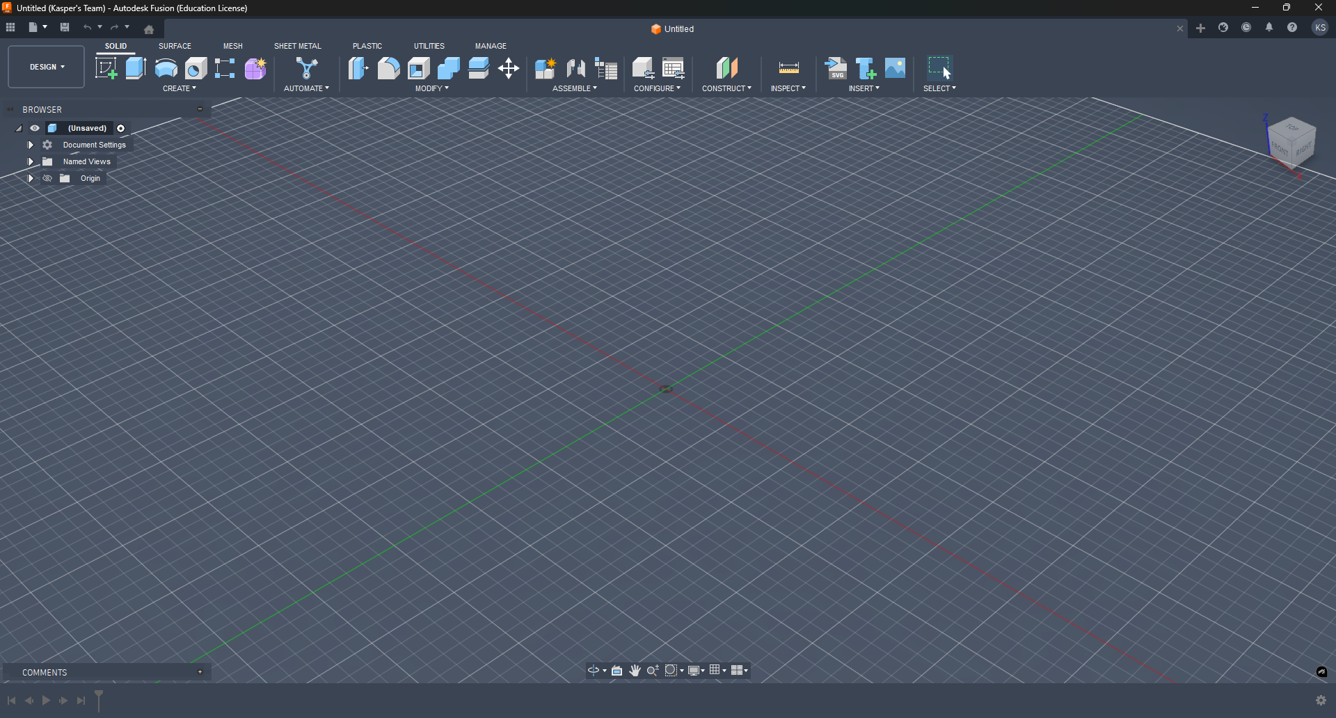
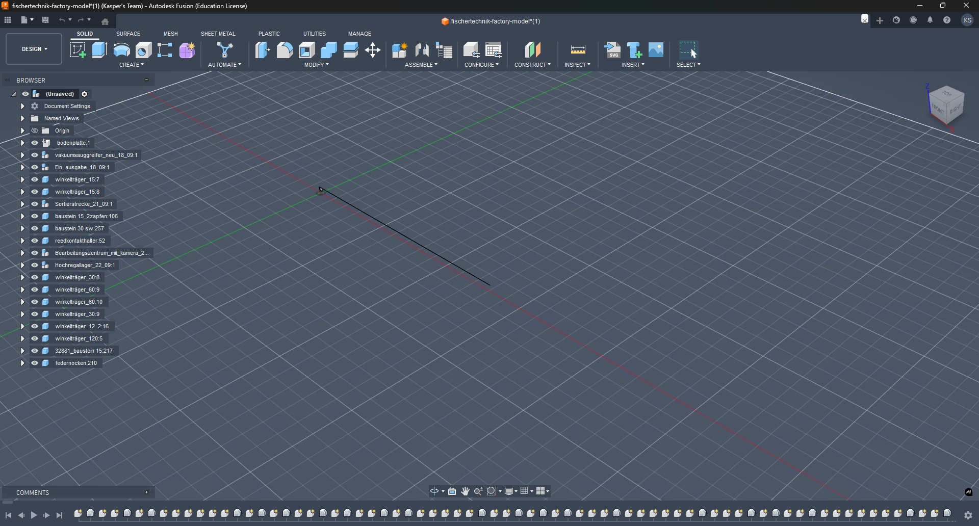
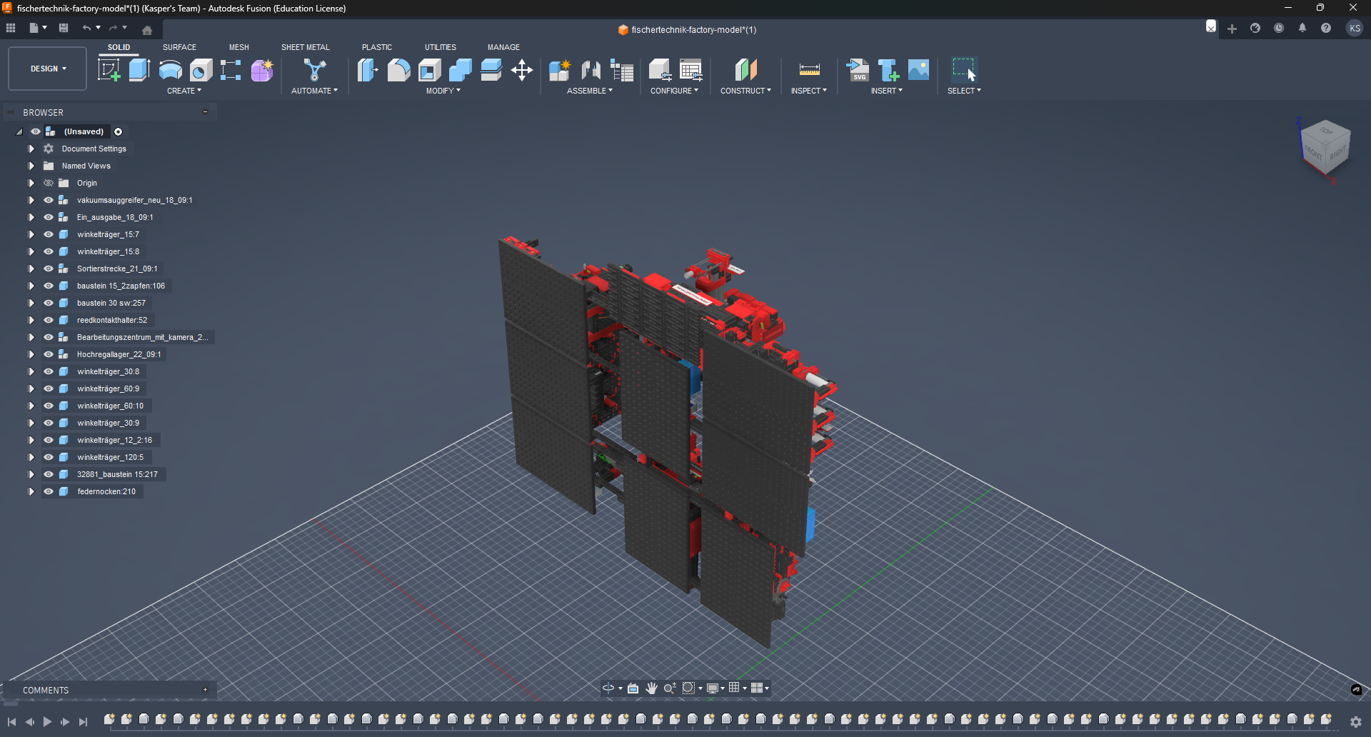
Start by opening Fusion 360. Ensure you have a valid license and the latest version installed. The interface should look similar to the image below.
Importing the STEP File
Navigate to File > Open or press Ctrl + O to open the dialog box.
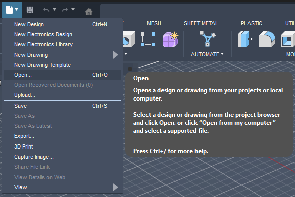
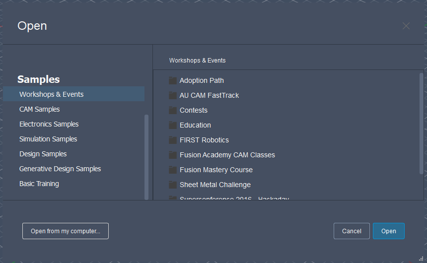
The following dialog box will appear. Select Open from my computer on the bottom left corner. This will allow you to select the .STEP file you want to import.
Note
In this example, the file fischertechnik-factory-model.STEP is used. This file contains the complete fischertechnik factory model and can be found here: Fischertechnik Factory Model.
Larger files may take longer to load. Be patient while the model is being imported.
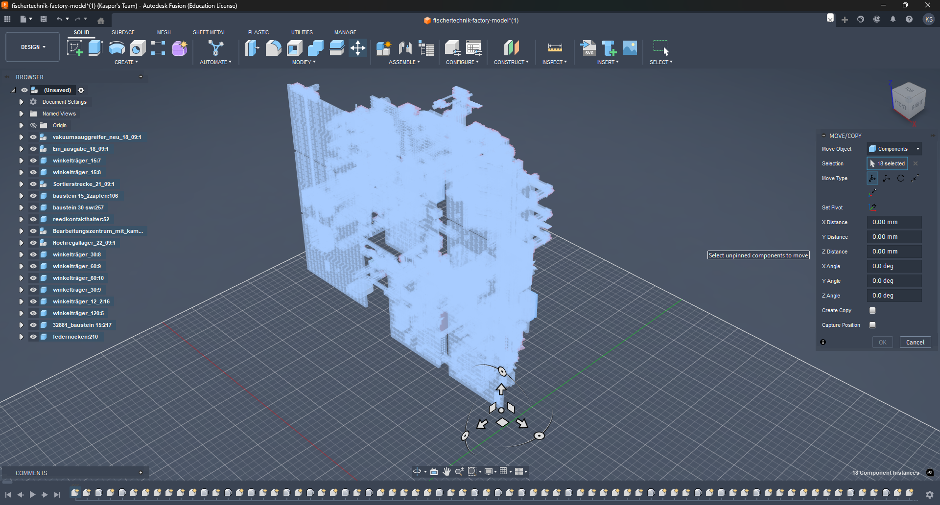
The file is successfully imported. However, the model appears broken, small, and rotated. This is a common issue when importing .STEP files from different CAD software. To fix this, we need to make some adjustments. Let's examine the issue in detail.
Fixing the Imported Model
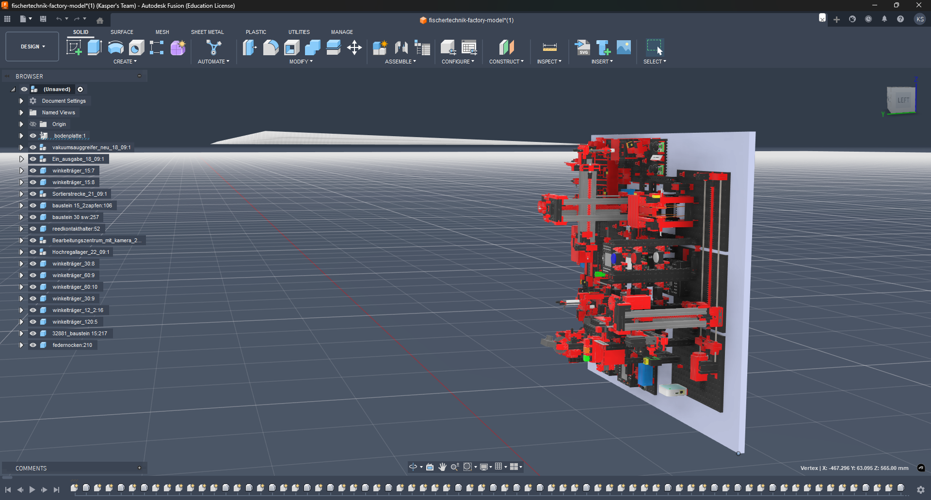
The following issues are present:
- Rotation: The model is rotated 90 degrees on the X-axis.
- Position: The model is not flattened to the ground.
- Broken Mesh: A large, white artifact is present.
- Unwanted Components: Included ground plane that is not needed.
Artifact Issue
Let's start by resolving the artifact issue. On closer inspection, it appears that it originates from the cover of the NFC reader.
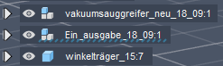
By clicking on the artifact, a small highlighted area appears on the component tree (left side). The highlight might be difficult to spot, but it is there under Ein_ausgabe_18_09.
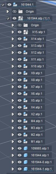
Extend the component tree item and continue to extend the items until you find the corrupted component called 161944-1.stp under 161944:1 > 161944.stp (1).
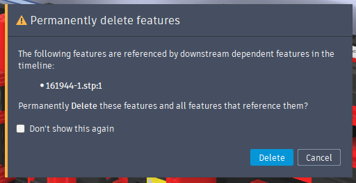
Delete the corrupted component by selecting it in the component tree and pressing Delete on your keyboard. A confirmation dialog will appear. Click Delete to delete the component.
The artifact is now successfully removed.
Removing the Ground Plane
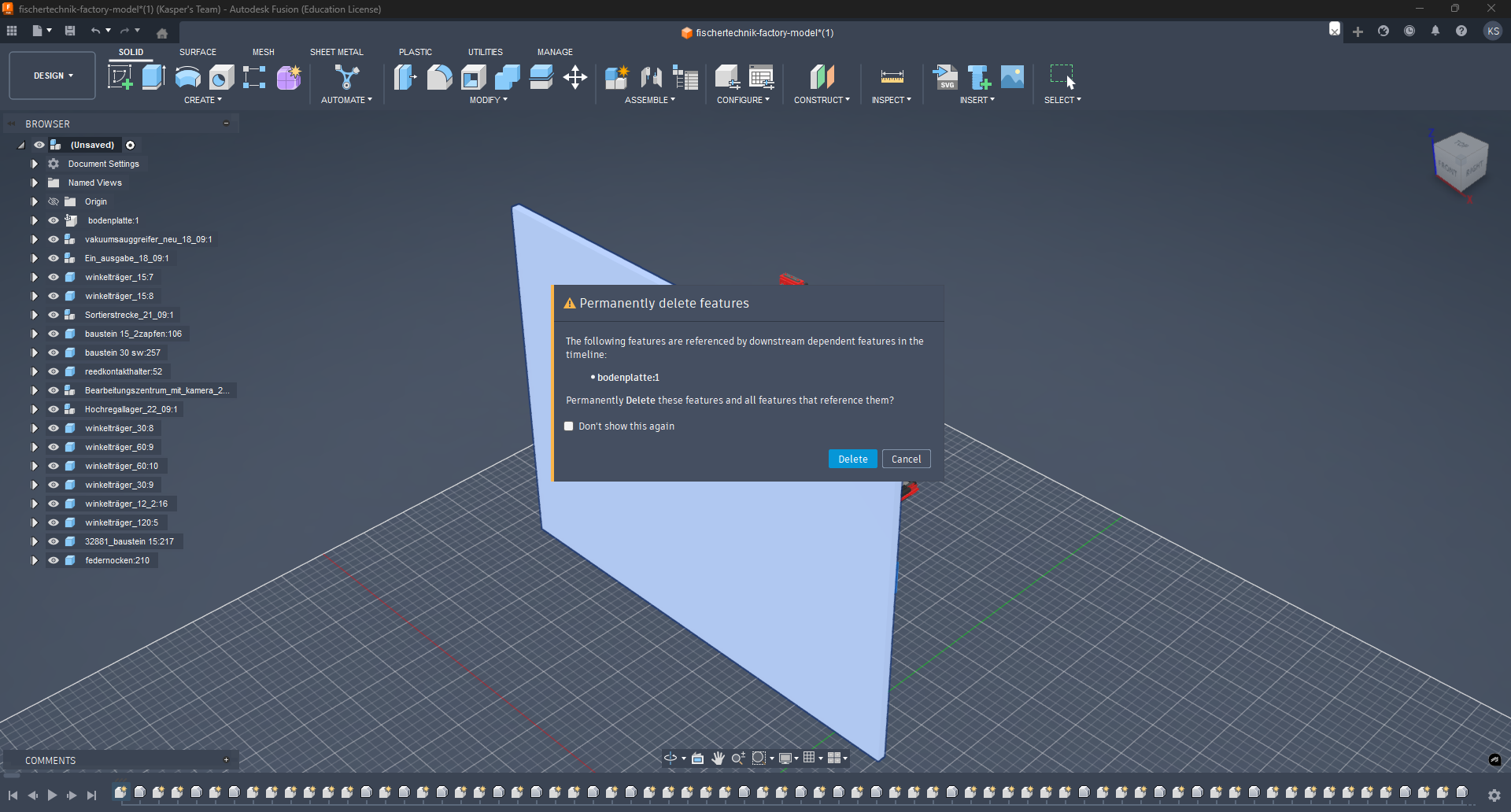
Select the ground plane in the component tree and press Delete on your keyboard. A confirmation dialog will appear just like before. Click Delete to remove the ground plane.
Fixing the Transformation
Currently, the model is rotated 90 degrees on the X-axis and floating in the air. To fix this, we need to rotate and flatten the model.
Select all components in the component tree by holding Shift and first clicking on the top component, then on the last component. This will select all components in between.
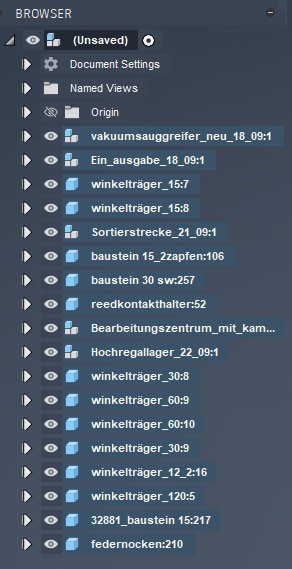
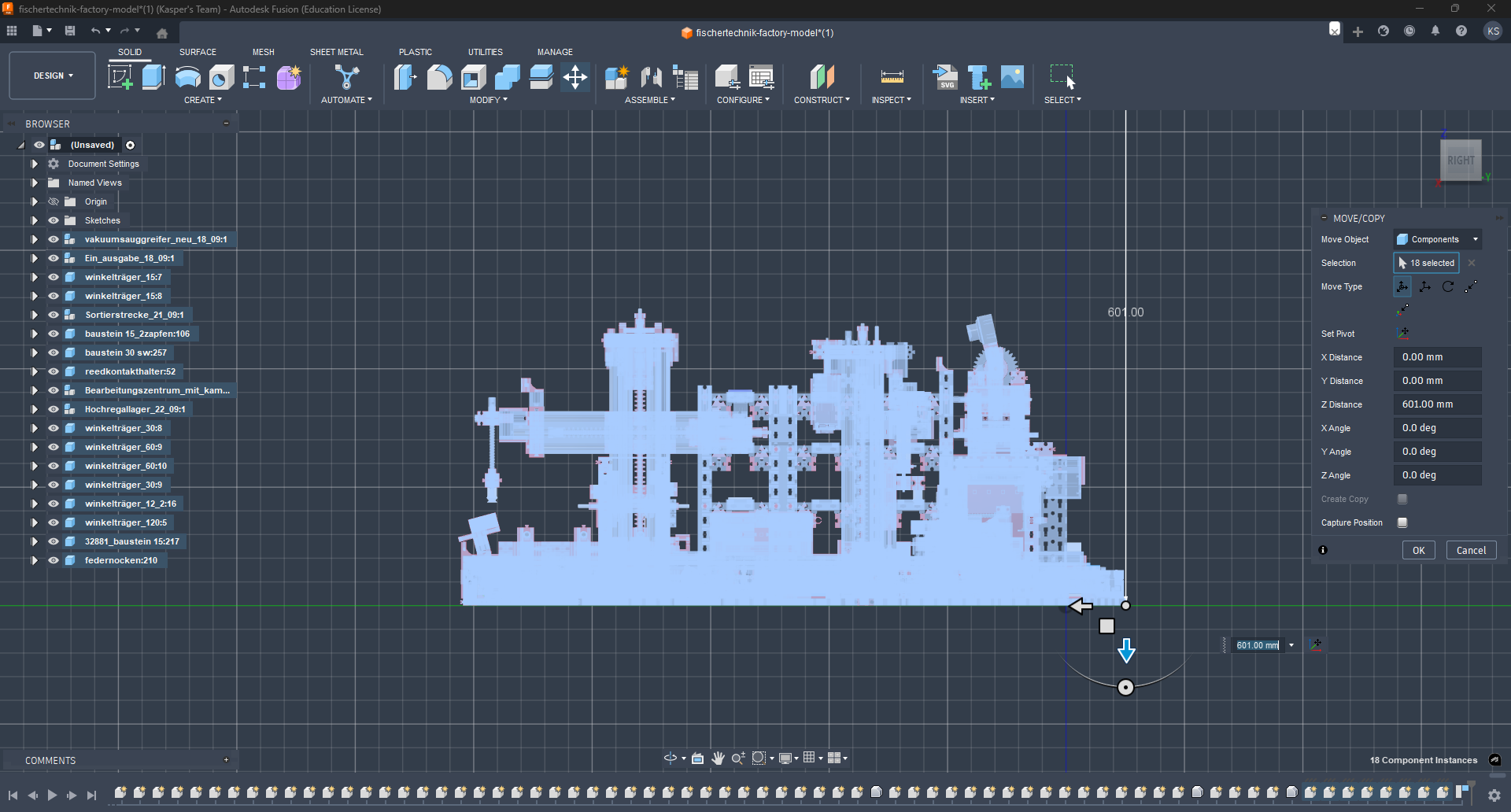
With all components selected, press M to activate the Move tool. A Gizmo will appear on the global pivot point of the selection and a dialog box on the right side.
To make the rotation easier, we change the pivot point to one of the bottom corners of the model. To do this, click on the Set Pivot button in the dialog box on the right side.

Note
Once done, do not forget to acknowledge the new pivot point by clicking again on the Set Pivot button.
The new rotation on the X-axis can be set to 90 degrees. Give it some time and the model will rotate to the correct position.
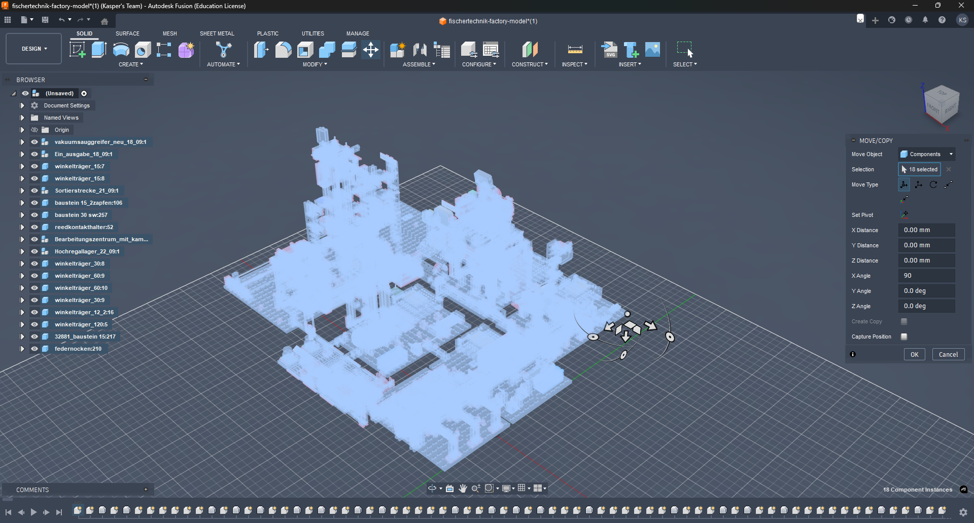
Next, we need to flatten the model. If you have chosen the bottom corner of the model as the pivot point, the offset to the ground is precisely 601.0 mm.
To flatten the model, input 601.0 mm in the dialog box for the Z-axis translation. This adjustment will align the model with the ground level.
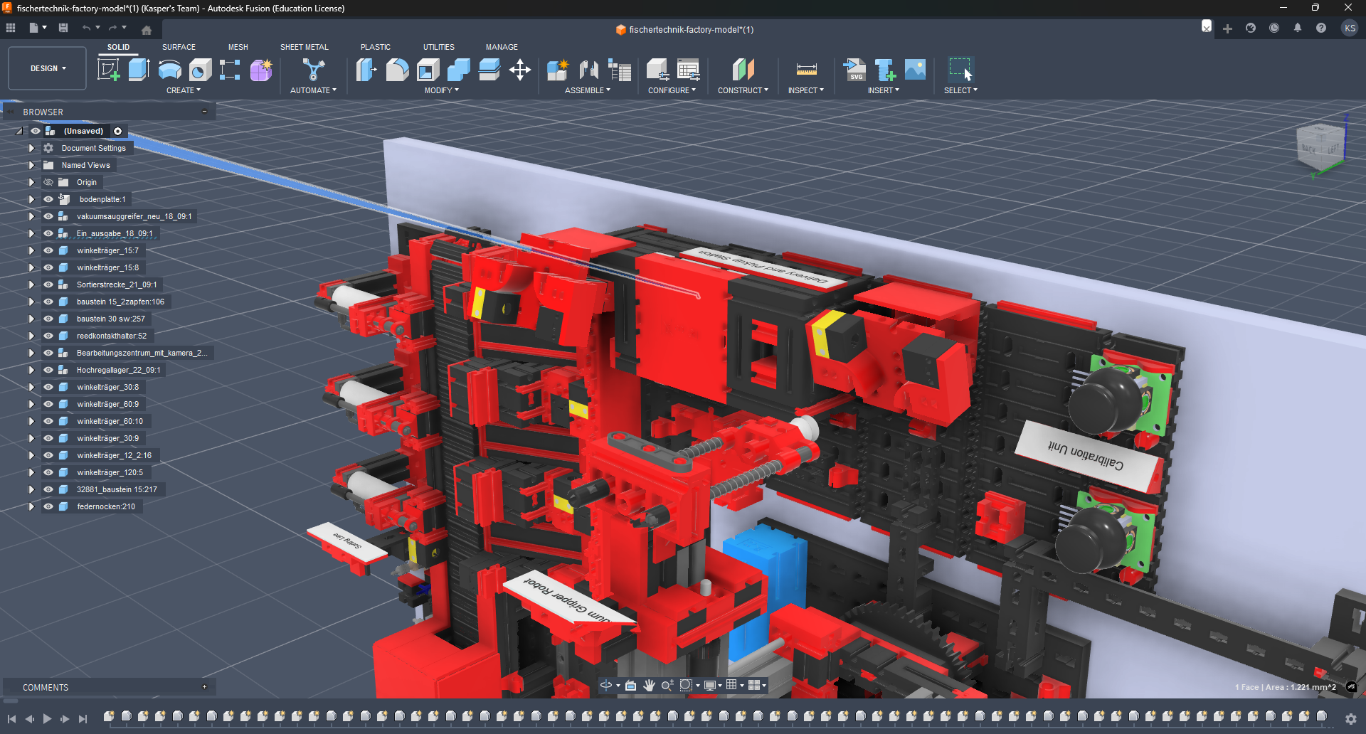
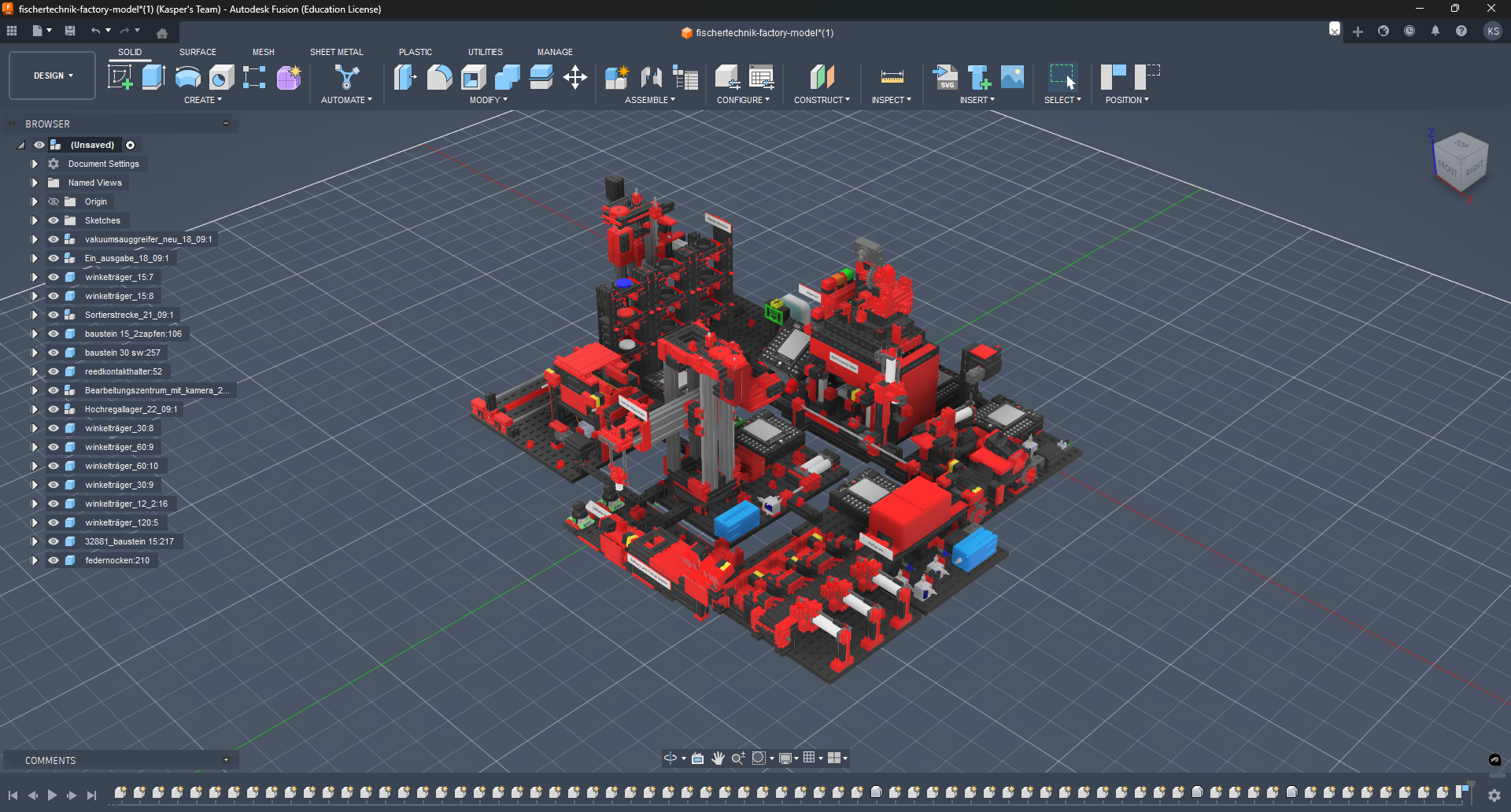
With these adjustments complete, the model is now correctly positioned and oriented. The final result should resemble the following:
Exporting the Model
For this example, we will export the Vacuum Gripper Robot (VGR). It is recommended to export the model as individual components rather than as a complete assembly to optimize file size and enhance performance.
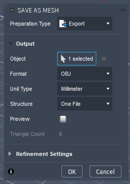
The VGR is contained within a component named vakuumsauggreifer_neu_18_09. Locate this component in the component tree, right-click on it, and select Save As Mesh from the context menu. This action will open the export dialog box on the right side of the interface. Retain the default settings and click OK to proceed with the export.
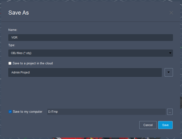
A file save dialog will appear, prompting you to specify a file name and location. Choose an appropriate name and directory for the exported model. In this demonstration, the file is named VGR.obj and saved to the D:\Tmp directory.
Note
The duration of the export process depends on the complexity of the model and your system's specifications. Allow sufficient time for the operation to complete, as Fusion 360 may become temporarily unresponsive during this process.
The model has now been successfully exported and is available in the specified directory. Fusion 360 can be closed at this point.
Importing the Model into Blender
Importing the model into Blender is a straightforward process. Begin by removing the default scene objects, which typically include a cube, camera, and light. To do this, select all objects in the scene by pressing A on your keyboard. Then, press X to delete the selected objects.
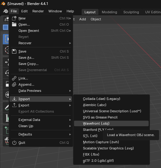
Next, navigate to File > Import > Wavefront (.obj) to open the import dialog box.
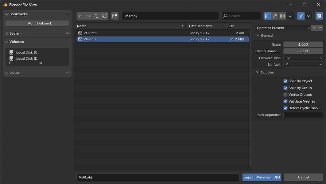
Select the previously exported file VGR.obj and check Split By Group in the import settings on the right side. This option will create separate objects for each group in the OBJ file, which is useful for maintaining the hierarchy of the model.
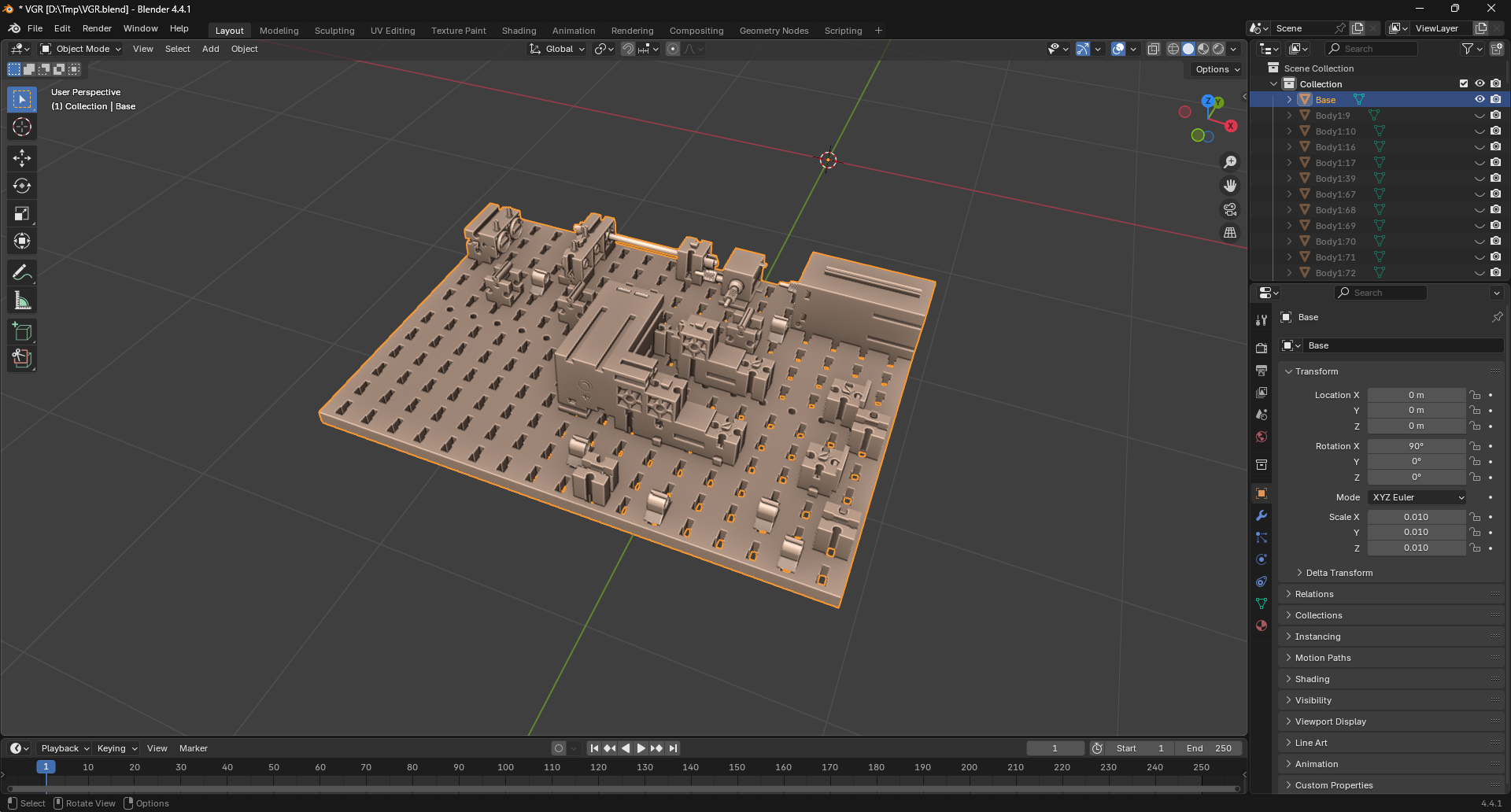
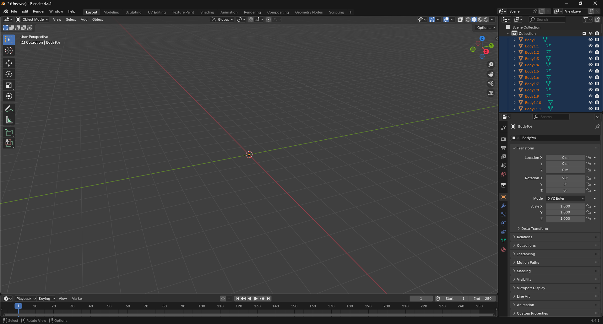
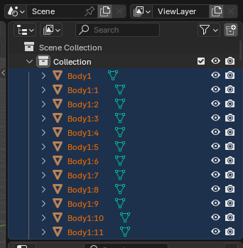
The model is now imported into Blender. However, although the collection tree on the top right side shows elements, the model is not visible in the viewport. This occurs because the scale of the model is significantly larger than the default Blender scene dimensions.
To address this issue, scale the model down. Ensure all objects are selected by pressing A on your keyboard and verifying that all text in the collection tree appears in orange.
Scale the model down by pressing S on your keyboard and entering 0.01 to reduce it to 1% of its original size. The model should now be visible in the viewport.
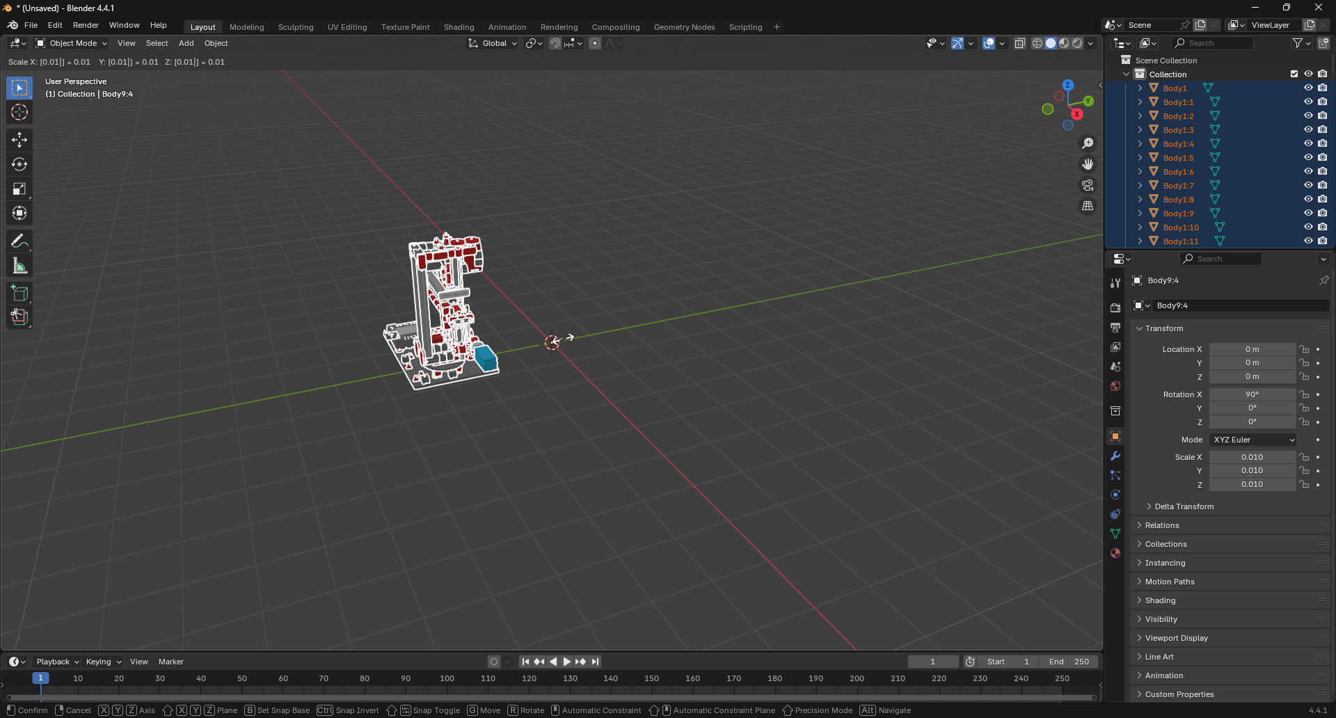
Apply the transformation by pressing Ctrl + A and selecting All Transforms from the context menu. This step is critical to ensure that the model maintains its correct size and proportions when exported to Unreal Engine and when applying modifiers in Blender.
Note
The model is slightly off-center. This is advantageous in our case as the offsets for each component will correspond directly with the original CAD model. The pivot point is correctly positioned at the center of the scene.
An inaccuracy can be observed on one of the labels in the model:

This completes the import process. The model is now ready for further adjustments and optimizations in Blender.
Some Theory
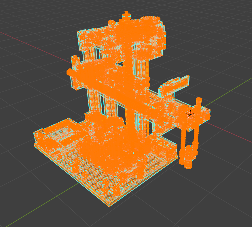
The model currently consists of individual Fischertechnik blocks. To optimize it for Unreal Engine, these components should be consolidated into a single object. This consolidation will reduce the number of draw calls and enhance performance in the game engine. Additionally, it will simplify the rigging process for the model.
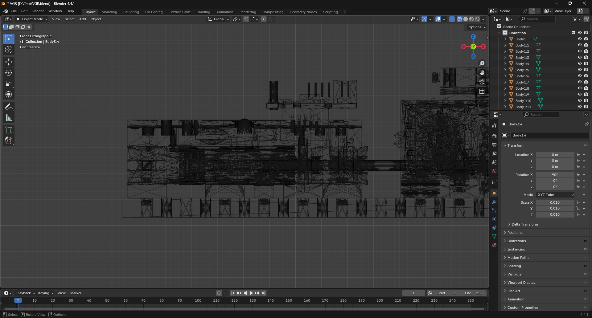
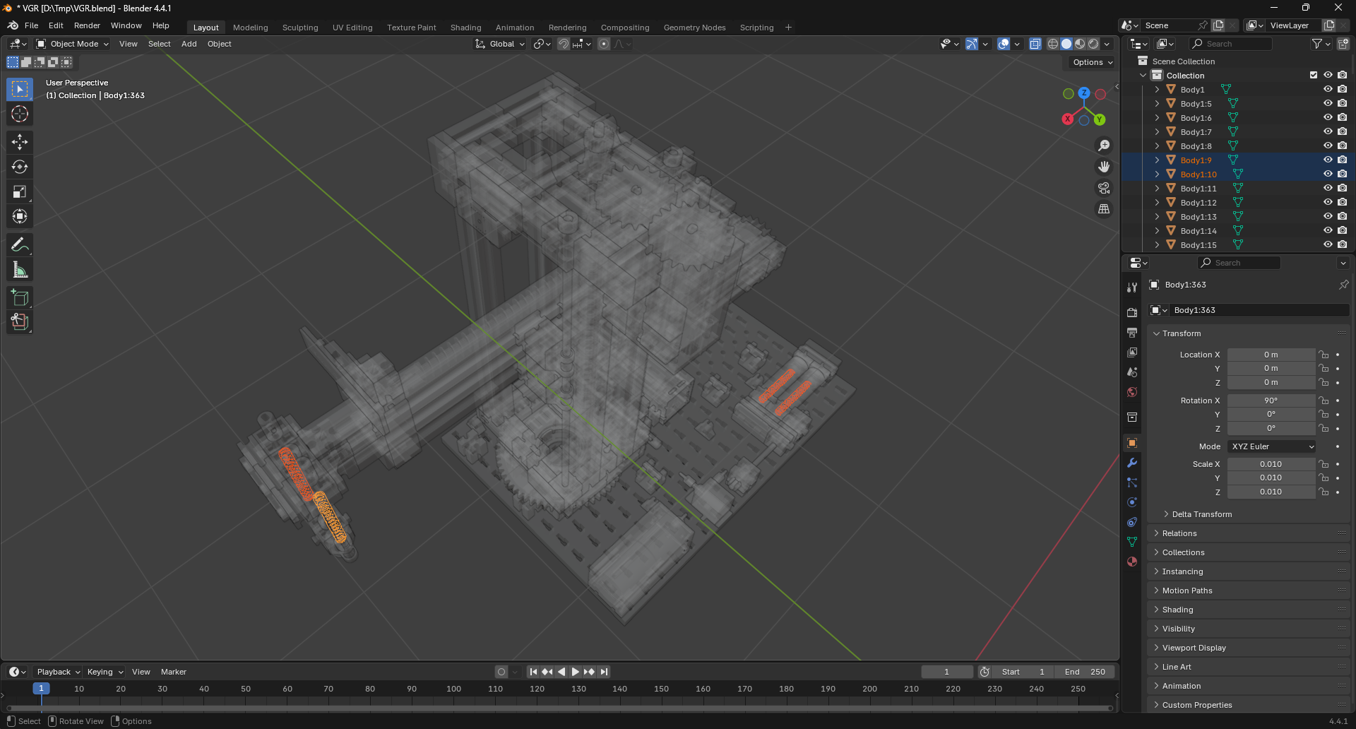
Optimization is essential as the model contains a complex and dense mesh. Switching to wireframe mode by pressing Z on the keyboard reveals a topology that is extremely intricate and inefficient for real-time rendering.
NURBS vs. Polygonal Meshes
The complexity and level of detail in the model stem from the different approaches used in CAD software versus 3D modeling software for defining and rendering geometry. CAD software utilizes NURBS (Non-Uniform Rational B-Splines) to create smooth surfaces and curves, which are mathematically defined. This approach allows CAD software to represent complex shapes with fewer polygons, resulting in a cleaner and more efficient model.
Conversely, most 3D software, including Blender and Unreal Engine, employs polygonal meshes to represent 3D objects. With this method, the geometry is defined by a collection of vertices, edges, and faces, which can result in a higher polygon count and more complex topology.
The preference for polygonal meshes in most 3D software is due to their ease of manipulation and efficiency in real-time rendering. Polygonal meshes are more compatible with game engines and real-time rendering techniques, making them the standard choice for 3D modeling in games and interactive applications. While NURBS are powerful for CAD applications, they are less efficient for real-time rendering and present challenges when integrated into a game engine environment.
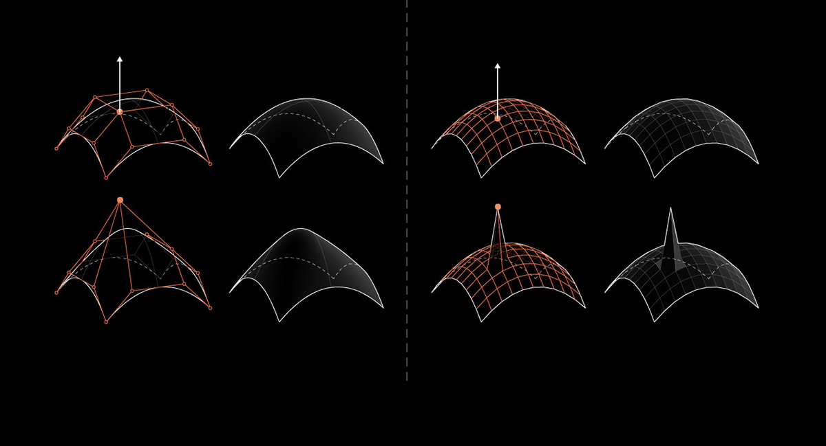
NURBS (left) vs. Polygonal Meshes (right)
For further information on this topic, refer to: NURBS vs. Polygonal Meshes.
Topology Optimization
Blender provides various tools and techniques for optimizing the topology of 3D models. During the subsequent optimization process, we will employ the following techniques:
- Decimation: This technique reduces the number of polygons in a mesh while preserving its overall shape and appearance. It is useful for simplifying complex models and improving performance in real-time applications.
- Joining: This technique combines multiple objects into a single mesh, reducing the number of draw calls and improving performance in game engines. It is particularly useful for models with many small components that can be grouped together.
- Merge by Distance: This technique combines vertices that are within a specified distance of each other, effectively reducing the overall vertex count and improving the model's topology.
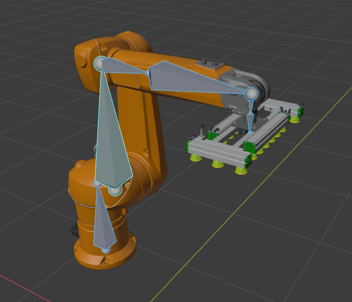
Rigging
Rigging constitutes the process of creating a skeletal structure for a 3D model, enabling animation and manipulation within game engines. This procedure involves defining bones, joints, and skinning weights to precisely control the model's movement and deformation.
For our implementation, rigging facilitates animation and control of the final model in Unreal Engine while maintaining a single mesh structure. Furthermore, rigging establishes a hierarchical framework where bones can be parented to other bones, creating effective movement chains. This hierarchical structure is particularly advantageous for components such as the gripper arm, which comprises multiple axes, gears, and various mechanical elements.
Removing Unused Components
The model represents the 9V version, which includes additional components not present in the 24V version being recreated. These extraneous components should be removed to reduce file size and complexity.
In the VGR model, the TXT controller is absent in the 24V version and can therefore be eliminated.
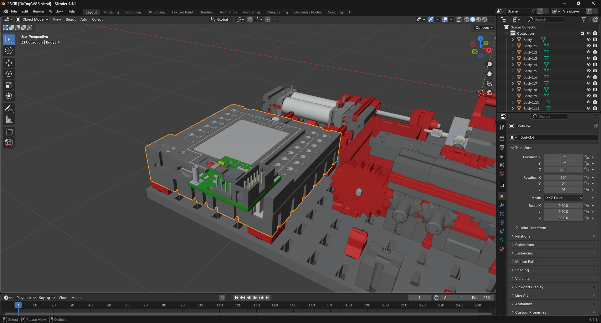
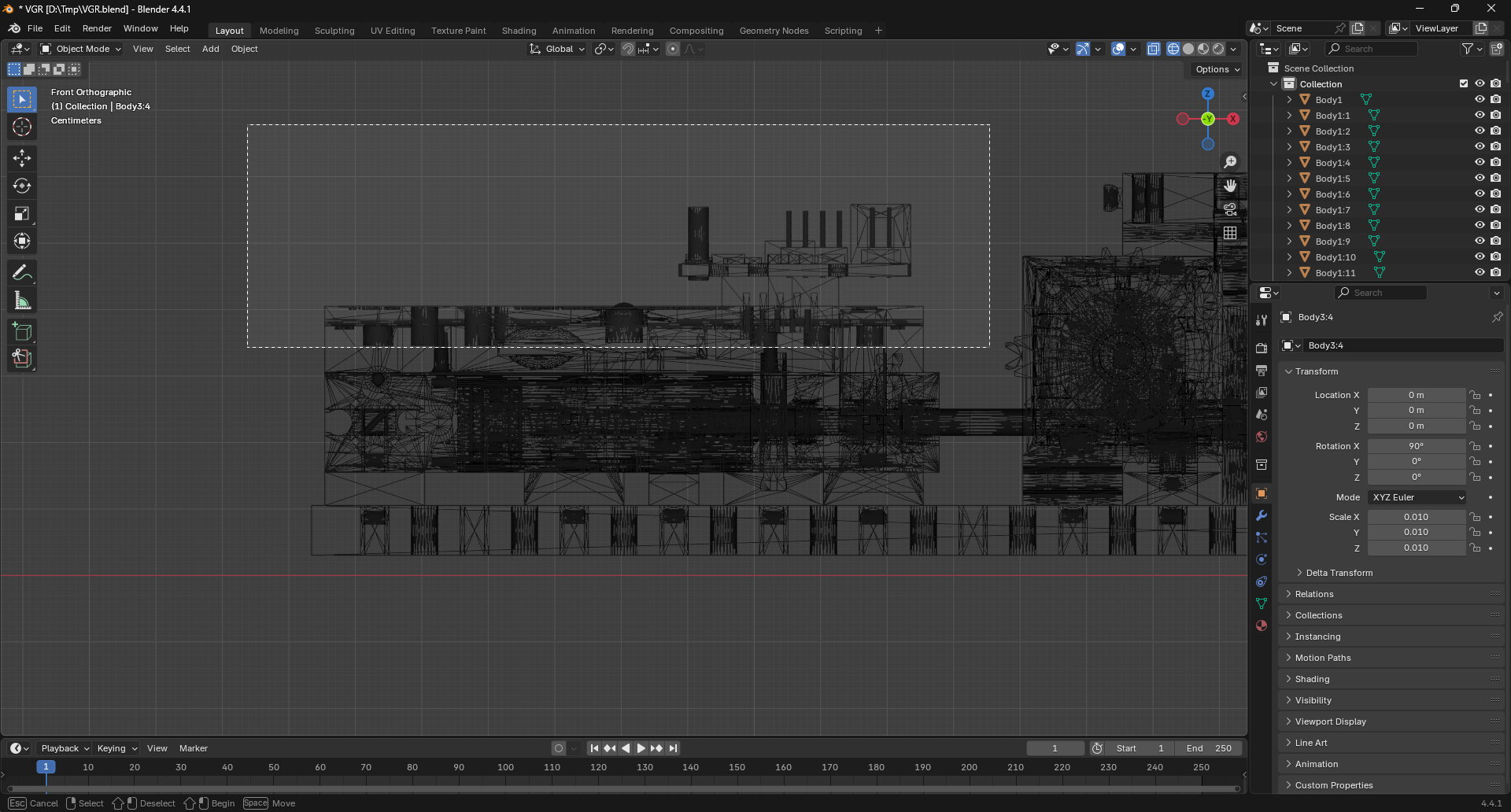
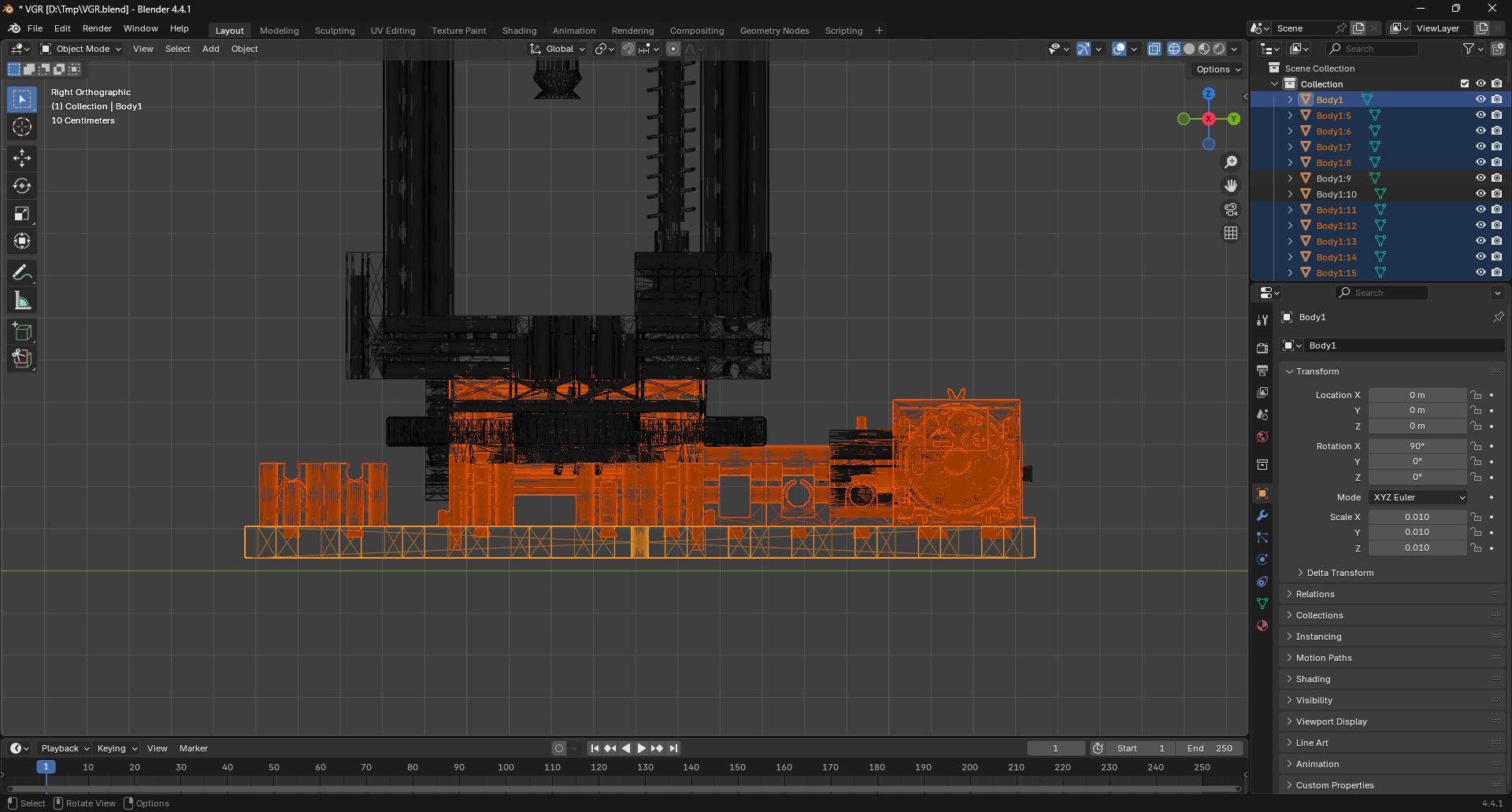
The TXT controller comprises multiple small components that are not connected to the main model, necessitating manual selection and deletion. For optimal component selection, switch to Orthographic View mode by pressing 5 on the numpad, followed by 1 to access the front view. This perspective facilitates comprehensive selection of all TXT controller components using the Select Box tool.
Danger
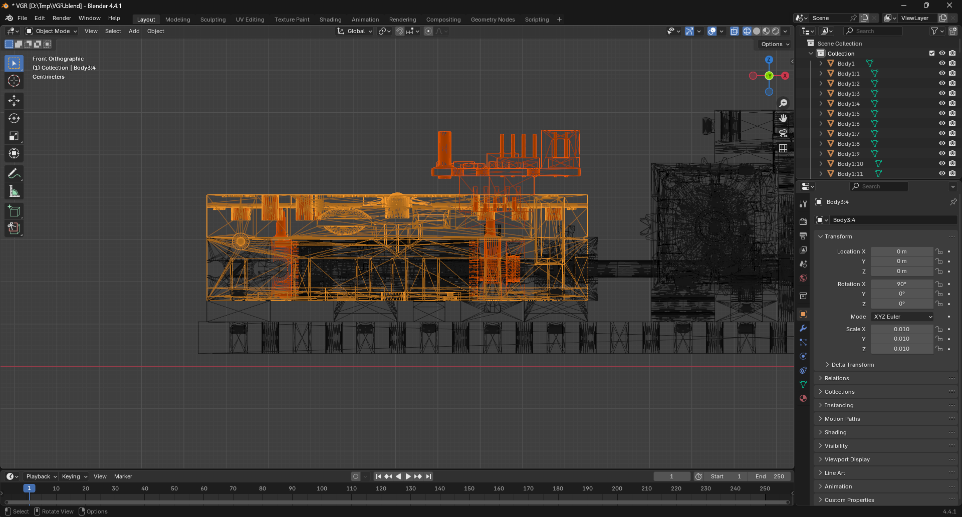
Ensure that no unintended components are selected prior to deletion. If additional components are inadvertently selected, deselect them by holding Shift and clicking on the specific component.
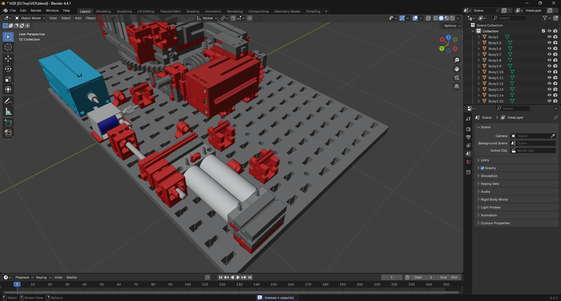
Delete the selected components by pressing X and selecting Delete from the context menu.
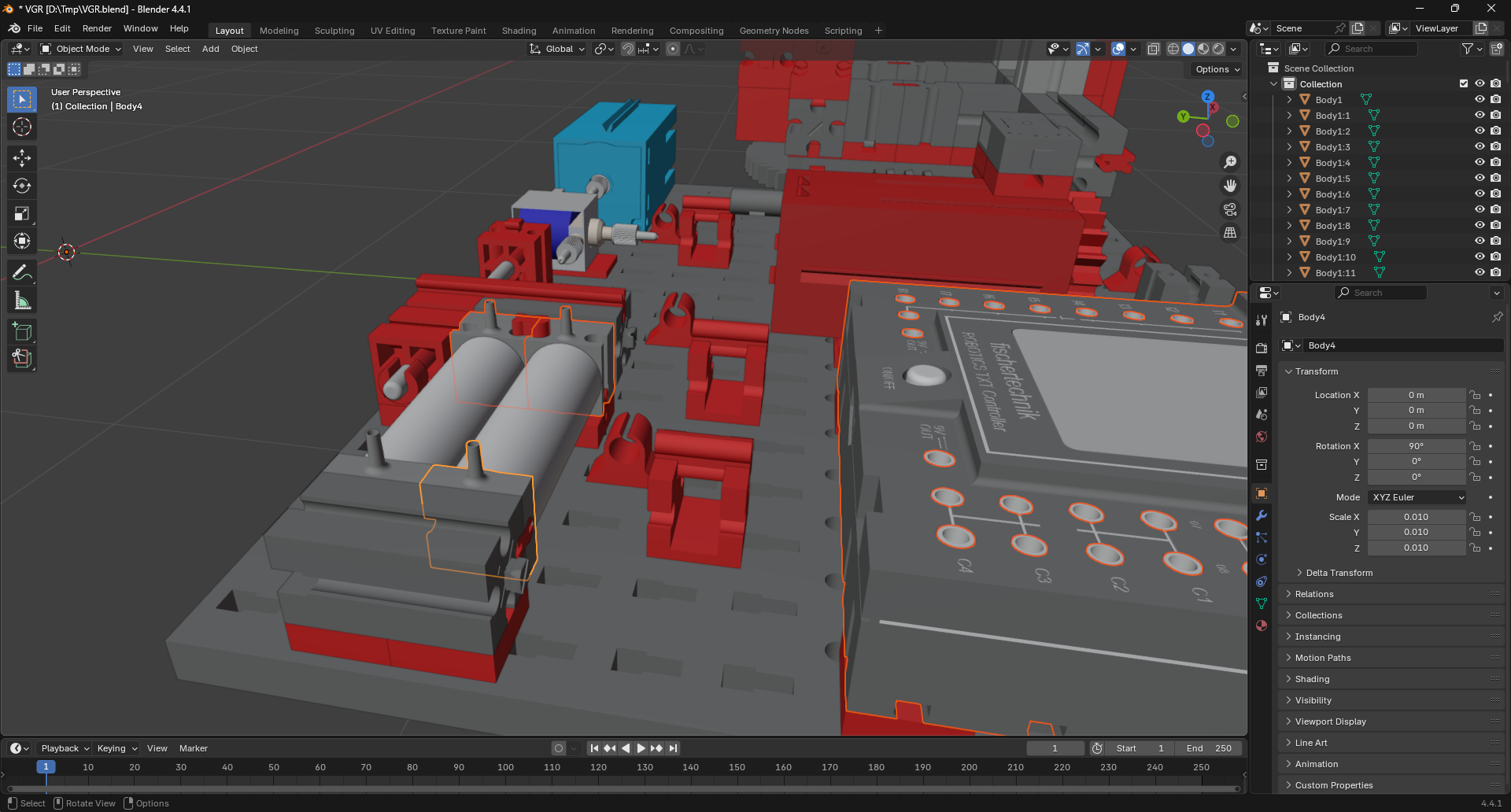
Additionally, four springs that are too small for practical use in the model should be removed. These springs are highlighted in the image below:
Note
Components can be temporarily hidden by selecting them and pressing H. This enhances visibility of smaller elements such as the springs inside the pneumatic cylinders. To restore hidden components, press Alt + H.
Remove the springs using the same deletion procedure as applied to the TXT controller.
Creating Groups
To facilitate efficient rigging, components should be organized into logical groups. This organization enables more effective rigging and maintains a clear hierarchical structure. The following section outlines the specific components requiring grouping and establishes criteria for their organization.
Example
Below is an example of how the components can be grouped. The example is based on the VGR model, which consists of the following components:
Tip
If you accidentally join the wrong components, you can easily separate them. Select the object that contains the unwanted components and press Tab to enter Edit Mode. Select one of the vertices of the component you want to separate. Press L to select all connected vertices. Then, press P and select Selection from the context menu. This action will separate the selected component into a new object.
Viewport Setup
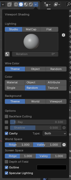
To help destinguish between the different components, it is recommended to change the following settings in the viewport:
- Color: Change the color to
Randomto make it easier to identify the different components. Each component will be assigned a different color. - Cavity: Enable the
Cavityoption to enhance the visibility of the model's edges and crevices.
Base
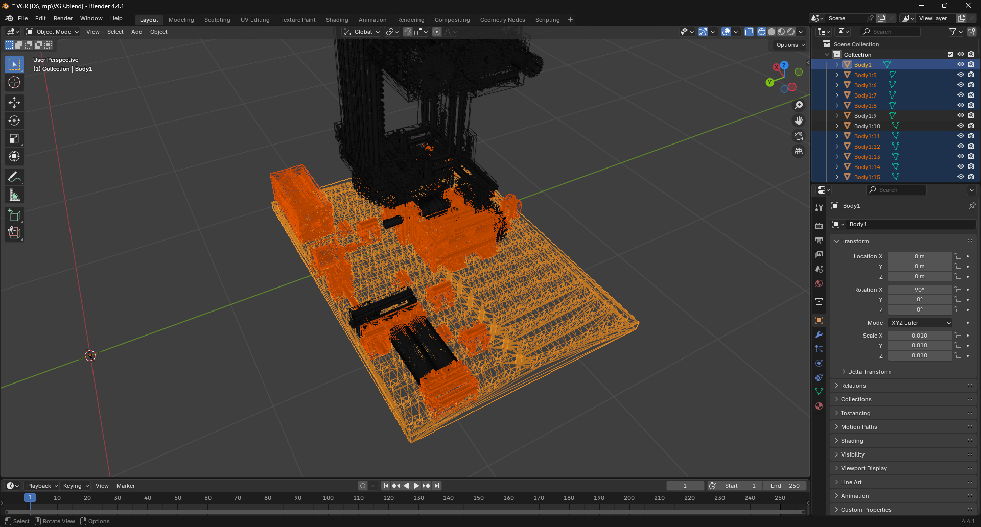
The base of the VGR serves as the foundation for the entire model. Select all components that constitute the base structure and remain stationary during operation.
Utilize the box selection method demonstrated in previous steps to select all base components.
The selection should include the following components as shown:
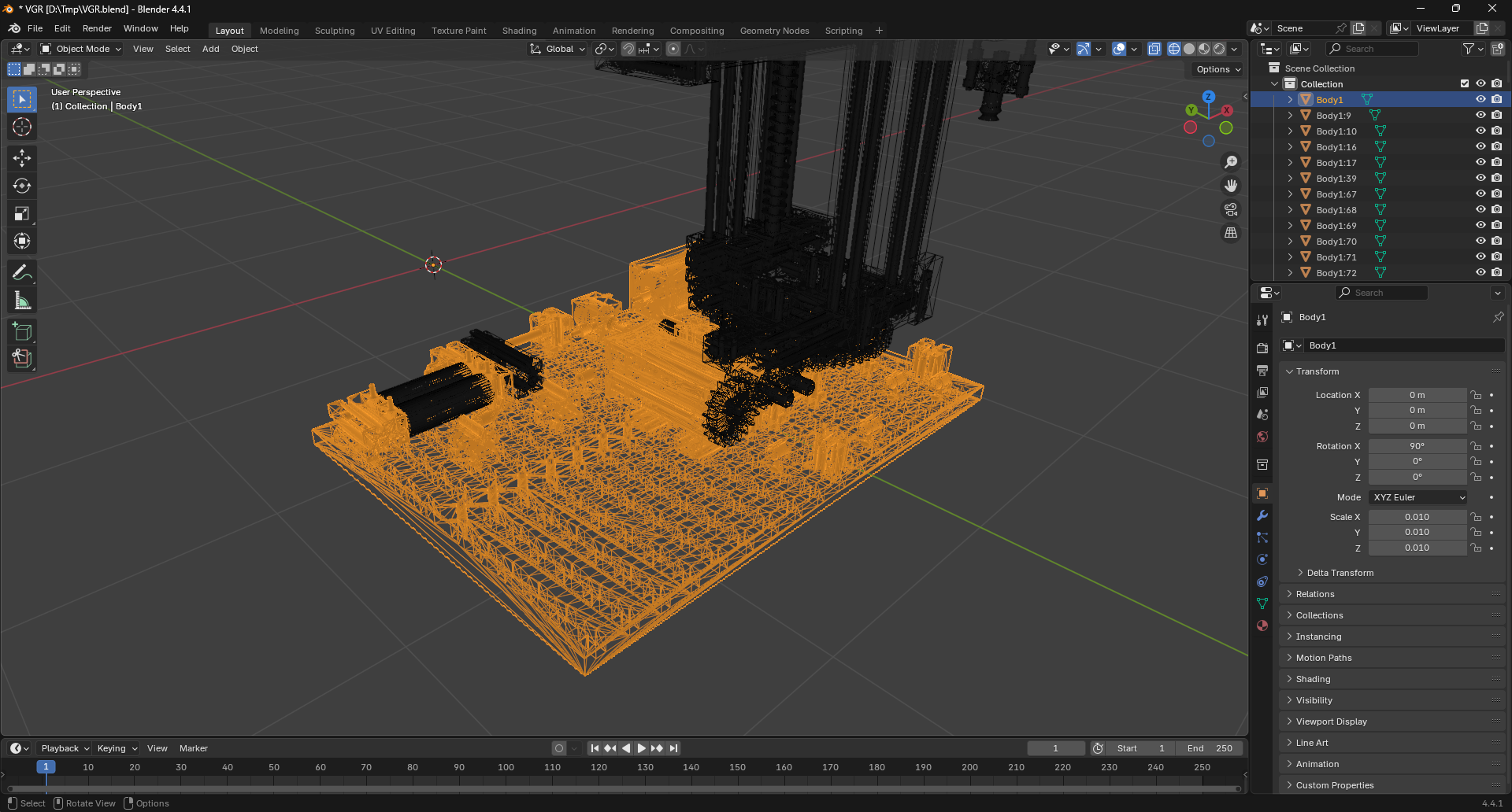
Ensure the base-plate is selected last, indicated by a brighter orange outline designating it as the active object in the selection. Execute the join operation by pressing Ctrl + J. This action will merge the selected components into a single object with the base-plate acting as the parent element.
Rename the newly created object to Base by pressing F3 to access the quick-rename dialog box.
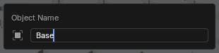
That completes the base group. The model should now resemble the following: